CHG 3316
TRANSPORT PHENOMENA
Assignment 2
1. Schematic Diagram:
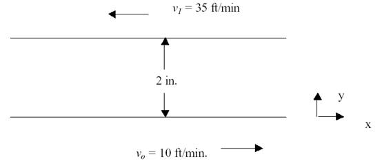
Referring to the above
figure, you are asked to:
1) Calculate the shear stress
on each plate when lower plate velocity is 10 ft/min. in the positive
x-direction and the upper plate velocity is 35 ft/min. in the negative
x-direction.
The plates are placed 2 inches
apart and the fluid viscosity between the plates remains constant at 150 cp.
2) Calculate the fluid
velocity at every 0.5 in. interval.
Solution:
It was clear from the question that the fluid had a constant viscosity.
i.e Newtonian fluid, that is why we are going to use Eq (2-8) from the text
book. (See also Figure 2-9 to see how viscosities are changing as well for
different fluids). Eq (2-8) is a first order ordinary differential equation. To
solve it, first you have to separate the variables.
After
variables separation, and by re-writing the general equation for the shear
stress, we have:
![]() (1 - 1)
(1 - 1)
Where ![]() is constant.
is constant.
Given
that the plates are 2 inches a part, this means that y1=0.0 and y2=2.
Also, Vo=10 ft/min and V1= - 35 ft/min (remember that the
two plates are moving in opposite directions). By doing the integration and
substitution in Eq (1) above:
![]()
This
gives ![]() (1-2)
(1-2)
Substituting,
![]()
![]()
![]()
![]()
Substituting in
eq. (2) gives
Now we
have the shear stress value.
To
work for number 2) and find the velocities at ![]() in., 1 in, and 1
in., 1 in, and 1![]() in.,
distance from the lower plate, we will use Eq(2), since the shear stress and
the viscosity remain unchanged and constant, then:
in.,
distance from the lower plate, we will use Eq(2), since the shear stress and
the viscosity remain unchanged and constant, then:
![]()
or ![]()
![]() (1-3)
(1-3)
For any value of y![]() :
:
![]() (1-4)
(1-4)
As a result, the
following are equal:
![]()
or  or
or 
Also  and
and ![]()
In the same way, ![]()
So at ![]() in.,
in., ![]()
At ![]() in.
in. ![]() , and at
, and at ![]() in.
in. ![]()
Results:
|
X value (inches) |
Velocity (ft/min) |
|
0.0 |
10 |
|
0.5 |
-1.25 |
|
1.0 |
-12.5 |
|
1.5 |
-23.75 |
|
2.0 |
-35 |
Comments: It can be
clearly seen from the velocities in the table that the fluid is moving toward
the negative x-direction following the resultant velocity vector.
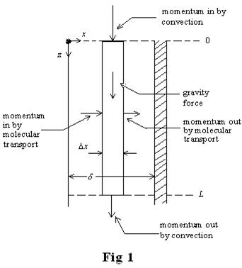
2. Oil is flowing down (in the
z-direction) a vertical wall as a film 1.7 mm thick. The oil density is 820 ![]() and the
viscosity is 0.20 Pa s.
and the
viscosity is 0.20 Pa s.
a) Draw a schematic diagram of
the system, choose your shell and show it in the diagram, and do a shell momentum
balance. Make sure you show your axes, momentum in and out directions, clearly in
the diagram.
b) Develop an expression for
the velocity ![]() as a
function of x,
as a
function of x,![]() , the thickness of the layer of liquid and relevant
fluid properties.
, the thickness of the layer of liquid and relevant
fluid properties.
c) What is the maximum
velocity, ![]() ?
?
d) Derive an expression for the
average velocity, ![]() , relative to the maximum
velocity.
, relative to the maximum
velocity.
Solution: (a) Control volume for falling film at steady state:
b) In order to develop an expression for the
velocity ![]() as a function of x,
as a function of x,![]() , the
thickness of the layer of liquid and relevant fluid properties, we have to perform momentum
balance at the Cartesian coordinates at steady state:
, the
thickness of the layer of liquid and relevant fluid properties, we have to perform momentum
balance at the Cartesian coordinates at steady state:
![]()
![]()
![]()
![]()
![]()
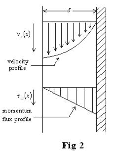
![]() momentum-flux profile is linear (figure 2)
& Max. value is at the wall.
momentum-flux profile is linear (figure 2)
& Max. value is at the wall.
For a Newtonian
fluid using
![]() ®
® ![]() and
and ![]()
Boundary condition
to evaluate the integration constant:
![]() at
at ![]()
![]()
So, vz becomes as follows:
 (3- 1)
(c)
Max. Velocity occurs at is at ![]() as can be seen from
the velocity profile shown in Fig 2. Using equation 3-1 and setting x=0 results
in the maximum velocity as shown:
as can be seen from
the velocity profile shown in Fig 2. Using equation 3-1 and setting x=0 results
in the maximum velocity as shown:
![]() (3-2)
(3-2)
(d) To
derive an expression for
the average velocity,![]() , we have to
integrate over the area (along both the width and the thickness as well) as
follows:
, we have to
integrate over the area (along both the width and the thickness as well) as
follows:
![]()

![]() (3 - 3)
(3 - 3)
and by
comparing 3-2 to 3-3 it can be seen that:
![]() (3-4)
(3-4)
Due Friday, October 7, 2011 in
the assignment box at 4:00 p.m.